


6502 Illegal Opcodes in the Siemens PC 100 Assembly Manual (1980)
6502 Illegal Opcodes in the Siemens PC 100 Assembly Manual (1980)
by Michael SteilThe 6502’s “illegal” opcodes were of intense interest to home computer enthusiasts, and analyses were published in various magazines. But one would have never expected a company like Siemens to document illegal opcodes in a programming manual from 1980.
The PC 100 Assembly Manual
The Siemens PC 100 is basically a Rockwell AIM-65 single-board computer in a case, featuring a 6502 processor, integrated keyboard, LED display, and thermal printer, tailored for educational and development purposes with localized documentation and modified ROMs.
Siemens’ German-language manuals were largely based on Rockwell’s originals, but shuffled the contents. Of particular interest is the assembly manual:
(124 pages, 17 MB)
It consists of:
| Assembler-Handbuch | Rockwell | Description |
|---|---|---|
| Chapters 1–9 | User’s Guide, Chapter 5 | Assembler Reference |
| Chapter 10 | Programming Manual, Appendix B | 6502 Reference |
| Chapter 11 | User’s Guide, Chapter 3 | Monitor Reference |
| Chapter 12 | – | Tables |
“Special Instructions”
The 6502 Reference has three extra pages at the end describing “Sonderbefehle” (“special instructions”) that were not in the original MOS/Rockwell 6502 reference that this chapter is a translation of. We can assume this was original research by Siemens.
Here is the translated transcription:
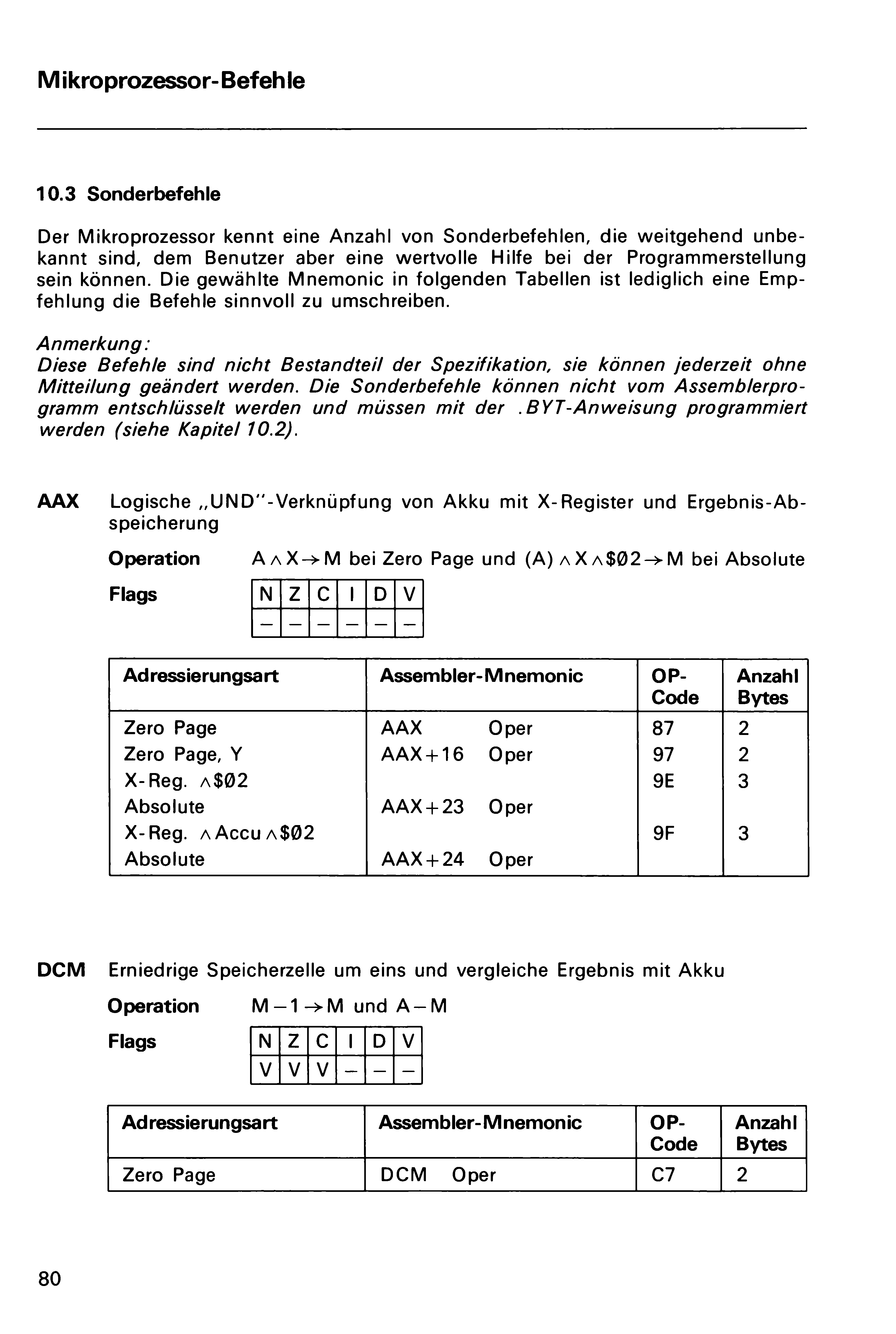
10.3 Special Instructions
The microprocessor recognizes a number of special instructions that are largely unknown but can provide valuable assistance to the user in program development. The chosen mnemonics in the following tables are merely recommendations for effectively representing these instructions.
Note:
These instructions are not part of the specification and may be changed at any time without notice. The special commands cannot be decoded by the assembler program and must be programmed using the .BYT directive (see Chapter 10.2).
AAX Logical “AND” operation between the accumulator and X-register, with result storage.
Operation A ∧ X → M with Zero Page und (A) ∧ X ∧ $02 → M with Absolute
Flags
| N | Z | C | I | D | V |
|---|---|---|---|---|---|
| – | – | – | – | – | – |
| Addressing Mode | Assembler Mnemonic | OP CODE | No. Bytes | |
|---|---|---|---|---|
| Zero Page | AAX Oper | 87 | 2 | |
| Zero Page, Y | AAX+16 Oper | 97 | 2 | |
| X-Reg. ∧ $02 | Absolute | AAX+23 Oper | 9E | 3 |
| X-Reg. ∧ Accu ∧ $02 | Absolute | AAX+24 Oper | 9F | 3 |
DCM Decrement memory location by one and compare result with accumulator.
Operation M – 1 → M and A – M
Flags
| N | Z | C | I | D | V |
|---|---|---|---|---|---|
| V | V | V | – | – | – |
| Addressing Mode | Assembler Mnemonic | OP CODE | No. Bytes |
|---|---|---|---|
| Zero Page | DCM Oper | C7 | 2 |
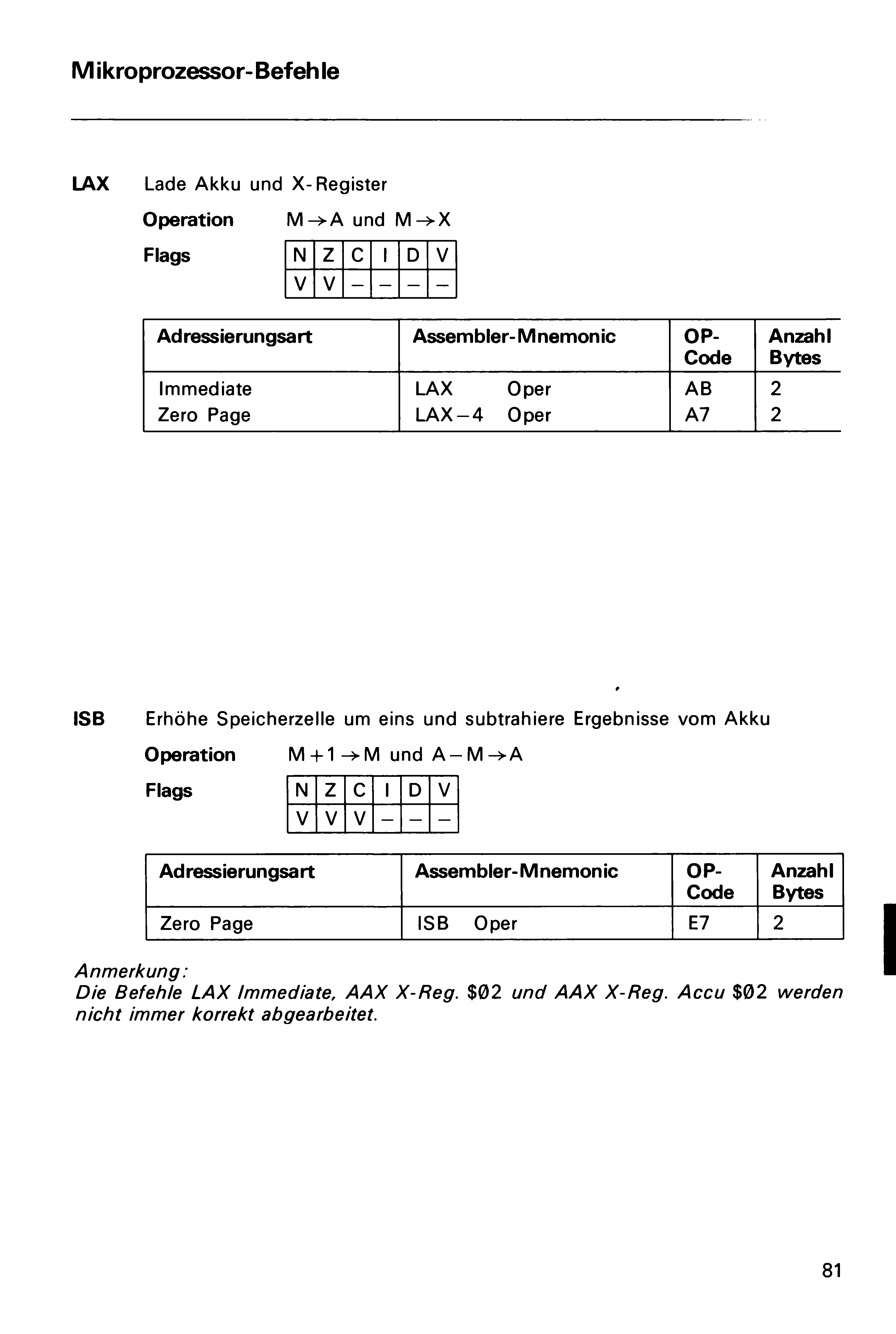
LAX Load accumulator and X register
Operation M → A and M → X
Flags
| N | Z | C | I | D | V |
|---|---|---|---|---|---|
| V | V | – | – | – | – |
| Addressing Mode | Assembler Mnemonic | OP CODE | No. Bytes |
|---|---|---|---|
| Immediate | LAX Oper | AB | 2 |
| Zero Page | LAX-4 Oper | A7 | 2 |
ISB Increment memory cell by one and subtract result from accumulator
Operation M + 1 → M and A – M → A
Flags
| N | Z | C | I | D | V |
|---|---|---|---|---|---|
| V | V | V | – | – | – |
| Addressing Mode | Assembler Mnemonic | OP CODE | No. Bytes |
|---|---|---|---|
| Zero Page | ISB Oper | E7 | 2 |
Note:
The instructions LAX Immediate, AAX X reg $02 and AAX X reg accu $02 are not always processed correctly.
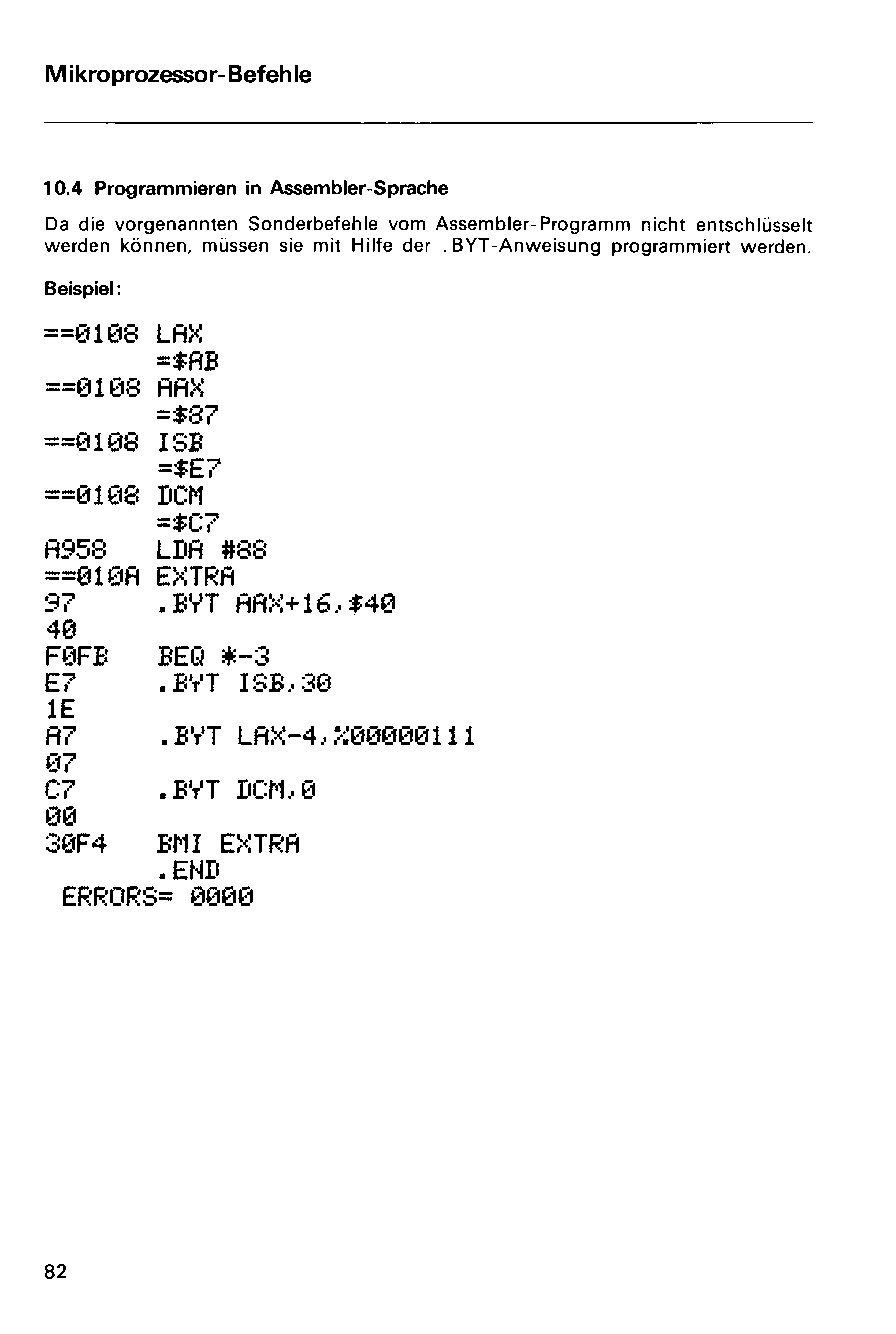
10.4 Programming in Assembly Language
Since the special instructions mentioned above cannot be decoded by the assembler program, they must be programmed using the .BYT directive.
Analysis
| Opcodes | Siemens | Mnemonic | Modern | Mnemonic | Comment |
|---|---|---|---|---|---|
| 87/97 | AAX | SAX | Correct. Also exists with izx/abs addressing modes. | ||
| 9E/9F | AAX | SHX/SHA | It’s aby, not abs. Also, their constant ($02) is actually the high-byte of the instruction address. (It should not be grouped with the other “AAX” opcodes.) | ||
| C7 | DCM | DCP | Correct. Also exists with zpx/izx/izy/abs/abx/aby addressing modes. | ||
| AB | LAX | LAX | Basically correct. The documented unstability comes from bits of the A register sometimes bleeding into the calculation. (More info) | ||
| A7 | LAX | LAX | Correct. Also exists with zpy/izx/izy/abs/aby addressing modes. | ||
| E7 | ISB | ISC | Correct. Also exists zpx/izx/izy/abs/abx/aby addressing modes. |
All in all:
- They got the ones they designated as “stable” right, but were missing many addressing modes.
- They got 9E/9F wrong (which they designated as “unstable”), probably by not testing enough inputs combinations.
- They got AB right (actually unstable), but they did not research the root of the instability further.
We can assume that this is either original research by a Siemens author – or they copied it from some other source. If the information had come from MOS or Rockwell, they would surely have
- listed all addressing modes.
- not added a statement like “The instructions […] and […] are not always processed correctly.” – or better yet, omitted the unstable ones.
Credits
Thanks to Gerald Schiepeck for his AIM-65 and PC 100 exhibition at the VCFE 2025, and Marco Baye for bringing the section in the assembly manual to my attention.
What's Your Reaction?
 Like
0
Like
0
 Dislike
0
Dislike
0
 Love
0
Love
0
 Funny
0
Funny
0
 Angry
0
Angry
0
 Sad
0
Sad
0
 Wow
0
Wow
0